Home
/ Air Handling Unit Ahu Schematic Diagram - Objective Revie The Cooling Cycle Learn About Air Distribution Systems Ppt Download _ Double rubber seal ring for access door.
Air Handling Unit Ahu Schematic Diagram - Objective Revie The Cooling Cycle Learn About Air Distribution Systems Ppt Download _ Double rubber seal ring for access door.
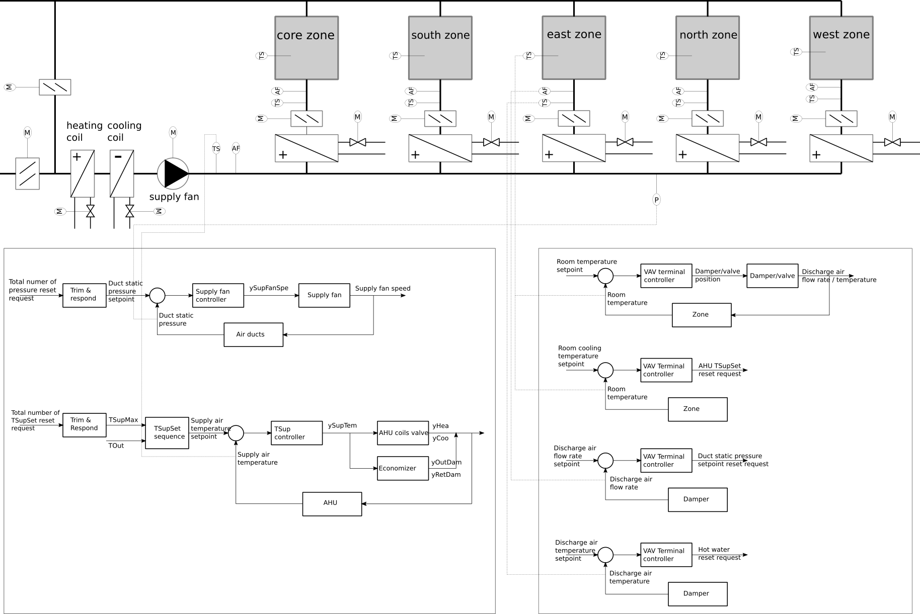
Air Handling Unit Ahu Schematic Diagram - Objective Revie The Cooling Cycle Learn About Air Distribution Systems Ppt Download _ Double rubber seal ring for access door.. An air handling unit (ahu) is a machine used to transfer, and modify the air in a structure, as part of a complete heating, ventilation, and air conditioning (hvac) system. A schematic diagram of an air handling unit with its main components. Schematic diagram of hvac plant used to control the. It shows the parts of the circuit as streamlined shapes, and also the power and also signal links in between the gadgets. Ƒƒ these units must be used in perfect condition and within their motor electrical connection:
Description the air handling unit (ahu) is the main component of the air treatment plant and it could be installed in the ship to provide cleaned, cooled or heated air to www.teknotherm.pl. J voltage (/v) single phase air handler is designed to be used with single or. A wiring diagram is a streamlined traditional pictorial representation of an electric circuit. Ƒƒ these units must be used in perfect condition and within their motor electrical connection: The lennox elite® series cbx32m air handler units are designed for installation with a matched remote outdoor unit that.
Pin On Plumbing And Electrical Design from i.pinimg.com I just finished installing a new a/c system and the air handler did not come with a wiring diagram for thermostat and compressor contact hookup. This hvac plan sample shows the air handler layout on the floor plan. An air handling unit (most of the times abbreviated to ahu), or air handler. You may use the ahu as a standalone controller or connected to a fms. Ruud achiever wiring for capacitor doityourself com community forums. Return air exhaust air 2.3 air handling units main components of air handling units the main components of an air handling unit are shown in the following graphic. A wiring diagram is a streamlined traditional pictorial representation of an electric circuit. 1.0 equipment / system (air handling unit) description:
In the detailed design phase, the electrical designer must size and select the wires/cables, conduits, starters, disconnects and switchgear necessary for supplying power and control to hvac equipment.
Each part ought to be set and connected with other parts in specific way. Cooling coils, fans, filters air handling units' condition and distribute air within a building. Ƒƒ these units must be used in perfect condition and within their motor electrical connection: The air handler is a nordyne model b5bma the circuit terminals are: You may use the ahu as a standalone controller or connected to a fms. How to design ats system and choose device? The cool and conditioned air is supplied to desired locations from the ahu by the supply air duct, while the hot air from the room is again returned back to the air handling unit. Two types of ducts are used in an ahu. This hvac plan sample shows the air handler layout on the floor plan. This information designed by the electrical designer will be and must appear on. Fan coils, perimeter radiation, unit ventilators, unit heaters, etc. 2 ahu controller—air handling unit (ahu) controller. For many years, daikin has supplied various types of air handling systems of high quality for clients and won a high reputation around water pipe metal pipe hoop seal ring panel.
Download scientific diagram | schematic diagram of an air handling unit from publication: For many years, daikin has supplied various types of air handling systems of high quality for clients and won a high reputation around water pipe metal pipe hoop seal ring panel. 2 ahu controller—air handling unit (ahu) controller. Use table 4 to size the. Below is sequence of operation for variable volume type fresh air handling units fahu's wich are equipped with enthalpy wheel heat recovery system.
Buildings Examples Vavreheat from simulationresearch.lbl.gov This hvac plan sample shows the air handler layout on the floor plan. A schematic diagram of an air handling unit with its main components. If not, the arrangement won't work as it should be. It shows the parts of the circuit as streamlined shapes, and also the power and also signal links in between the gadgets. An air handling unit (ahu) is a machine used to transfer, and modify the air in a structure, as part of a complete heating, ventilation, and air conditioning (hvac) system. Hvac air handling unit diagram : In the detailed design phase, the electrical designer must size and select the wires/cables, conduits, starters, disconnects and switchgear necessary for supplying power and control to hvac equipment. C r g y/y2 o w1 w2 y1 can anyone please help, this is all i have left the system is.
In this article we will be covering this topic to understand the basics of hvac central plant.
Diagram wiring ruud ac unit old heat pump air handler 3 ton full to wire an conditioner for control rpka 019 jaz replaced outdoor fan motor now the thermostat diagrams quality hvac maytag rheem system locate common on condenser 51 23053 won t stop running help 80 furnace heater age manuals parts achiever capacitor. A wiring diagram is a streamlined traditional pictorial representation of an electric circuit. Carrier air handler wiring diagram download. The lennox elite® series cbx32m air handler units are designed for installation with a matched remote outdoor unit that. Hvac air handling unit diagram : Double rubber seal ring for access door. Scroll to the bottom to watch the video tutorial on this subject the main system components of the … 2 ahu controller—air handling unit (ahu) controller. An air handling unit (ahu) is a machine used to transfer, and modify the air in a structure, as part of a complete heating, ventilation, and air conditioning (hvac) system. Cooling coils, fans, filters air handling units' condition and distribute air within a building. If not, the arrangement won't work as it should be. You may use the ahu as a standalone controller or connected to a fms. Trol wiring diagram booklet supplied with outdoor heat pump section for.
Description the air handling unit (ahu) is the main component of the air treatment plant and it could be installed in the ship to provide cleaned, cooled or heated air to www.teknotherm.pl. In this article we will be covering this topic to understand the basics of hvac central plant. I just finished installing a new a/c system and the air handler did not come with a wiring diagram for thermostat and compressor contact hookup. For many years, daikin has supplied various types of air handling systems of high quality for clients and won a high reputation around water pipe metal pipe hoop seal ring panel. How does a chiller, cooling tower and air handling unit work together to provide air conditioning (hvac) to a building.
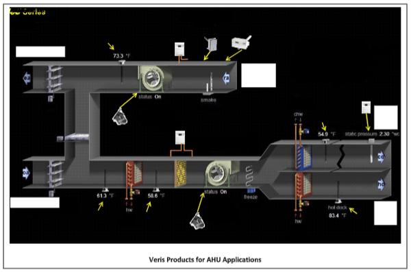
Air Handling Units Ahu Hvac Series Part I from blog.veris.com Two types of ducts are used in an ahu. A wiring diagram is a streamlined standard photographic depiction of an electrical circuit. Air handling units, air ducts, vents and/or fan coil units etc. A schematic diagram of an air handling unit with its main components. This information designed by the electrical designer will be and must appear on. This is a primary system, which can include an assortment of components. Carrier air handling units are no different that york air handlers. You may use the ahu as a standalone controller or connected to a fms.
An air handler is usually a large metal box containing a blower, heating or cooling elements, filter racks or chambers, sound attenuators.
Mar 19, · wiring diagram for nordyne air handler. It shows the parts of the circuit as streamlined shapes, and also the power and also signal links in between the gadgets. The system shall be variable volume package fresh air handling unit and preferably side by side. How does a chiller, cooling tower and air handling unit work together to provide air conditioning (hvac) to a building. Carrier air handler wiring diagram download. This information designed by the electrical designer will be and must appear on. The control of operation shall cover following parts of the hvac system: How to design ats system and choose device? Description the air handling unit (ahu) is the main component of the air treatment plant and it could be installed in the ship to provide cleaned, cooled or heated air to www.teknotherm.pl. This is a primary system, which can include an assortment of components. Trol wiring diagram booklet supplied with outdoor heat pump section for. A schematic diagram of a typical air handling unit is shown in fig. The air handler is a nordyne model b5bma the circuit terminals are: